
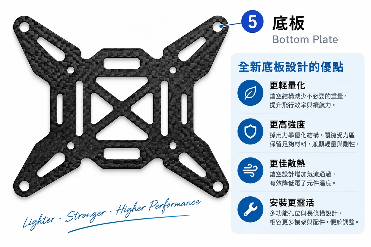
This is a carbon fiber bottom plate for a multirotor drone. It looks like nothing more than "a carbon sheet with a lot of holes in it," but from a machining standpoint, a cutout structure stacks five hard problems onto a single workpiece: the smallest inside corner radius limits tool diameter, removing more than half the material robs the workpiece of rigidity, every opening is another chance for exit-side delamination, hole positions directly affect flight, and the dust you cut is conductive. In this article we lay out every decision behind cutting this plate.
The One-Minute Version
- First measure the smallest inside corner radius on the drawing; it sets the maximum tool diameter. An R2 inside corner can't take a φ6 tool, so you have to drop to φ4 or smaller.
- The cutout ratio is the dividing line for workholding strategy. Online cutting services specify that CNC-milled parts must have less than 50% material removal; above that, parts tend to shift or break during cutting.
- Every opening has an exit side. With backing support, exit delamination can stay at 1.00–1.02 over a full tool life of 1,403 holes.
- Hole position errors don't cancel out. iFlight officially publishes in-house frame tolerances of ±0.1mm on hole diameter and ±0.2mm on thickness; ±0.05mm machining accuracy gives 2–4x margin at this scale.
- Cutting sequence makes or breaks the part: do the internal cutouts first and cut the outer profile free last, so the workpiece keeps its rigidity as long as possible.
- We cut it on the Carbon Pro EX: the 710×900mm working area fits several bottom plates on one full sheet, and integrated dust collection handles the conductive dust.
What does the bottom plate do in the frame, and why can't it just be light?
First, its role. The bottom plate is the datum surface of the whole aircraft: the FC/ESC stack, the battery, and the mounting points of all four arms converge here. It has to do three conflicting things at once: be light enough, be stiff enough, and let air flow through.
Why does stiffness matter? ArduPilot's official vibration damping documentation is blunt: "arms should be as rigid as possible"; frame flex is "a major source of unsynchronized vibration," and "frame flex introduces unwanted mechanical latency (hysteresis)." The bottom plate is the common support for the arms, so once it goes soft, the relative positions of the four arms start to drift.
This can be quantified. ArduPilot sets explicit vibration thresholds:
| VIBE value | Official assessment | What it means for bottom plate machining |
|---|---|---|
| < 15 m/s/s | Normal | Plate stiffness and mounting-point accuracy are both under control |
| < 30 m/s/s | Acceptable | Occasional peaks up to 30 are normal |
| > 30 m/s/s | May cause problems | Check mounting-point flatness and whether the plate has been weakened too much |
| > 60 m/s/s | Almost always causes position or altitude hold problems | Must be fixed |
| This is the most useful line we have when explaining "machining quality" to customers: how well the bottom plate was cut ultimately shows up in the flight controller's vibration log, not just in how it looks. | ||
Requirement 1: The smallest inside corner radius sets the maximum tool diameter
The first thing we do when we receive a drawing is not set parameters but find the smallest inside corner radius on it. A tool can't cut an inside corner smaller than its own radius: if you want an R2 inside corner, the tool can be no larger than φ4. That rule pushes some features straight from φ6 down to φ4 or even φ2.
The cutout features on this plate fall into roughly four types, each matched to a different tool diameter:
Cutout features annotated with tool diameters
Four feature types on one bottom plate; the smallest inside corner radius decides how large a tool each can use
Requirement 2: The cutout ratio decides the workholding strategy
This is the most underestimated aspect of cutout parts. The more material you remove, the harder it is to hold the remaining skeleton in place, and cutting forces don't shrink just because the workpiece got lighter.
Online cutting service SendCutSend has a written rule for CNC-milled parts: material removal must be under 50%, because above that parts tend to shift or break during cutting. It's a very practical dividing line.
Cutout ratio vs. workholding strategy
The higher the material removal rate, the more aggressive the workholding needs to be
Requirement 3: Every opening has an exit side
A solid plate only has exit delamination to worry about around one outer profile. With a cutout plate, every single opening is another thing to worry about. This plate has a dozen or so openings, which means a dozen or so chances.
The fix is simple, and its effect is backed by experimental data: give it backing support. In a long-duration experiment by Gutiérrez et al. in 2023, a backing plate pre-drilled with a matching hole array was placed under the workpiece and 1,403 holes were machined in a row; exit-side delamination stayed at 1.00–1.02 over the life of the entire tool.
We bond the whole workpiece in full contact with thin, high-bond double-sided tape to a spoilboard that has already been surfaced, so there is support directly under every opening. The spoilboard must be surfaced by the machine itself first. The point isn't to make it "flat"; it's to make it flat relative to this particular machine, and those are not the same thing.
The same study also notes that burr-type defects are not reduced by a backing plate. They come from cutting-edge rounding and are solved by changing tools. These are two problems that must be handled separately: delamination is about support, burrs are about tool condition.
Requirement 4: Hole position errors don't cancel out
The mounting holes on the bottom plate are the locating datums for the arms and the FC/ESC stack. A 0.1mm error in a single hole looks harmless, but the errors at four mounting points add up to an uneven mounting surface.
The most meaningful benchmark is actual industry practice. iFlight publishes its in-house manufacturing tolerances on the official spec pages of several frames:
| Item | Tolerance | Relative to ±0.05mm | Type of source |
|---|---|---|---|
| iFlight frame hole diameter | ±0.1 mm | 2× | Manufacturer's official spec page |
| iFlight frame thickness | ±0.2 mm | 4× | Manufacturer's official spec page |
| Carbon fiber waterjet job shop | ±0.23 mm | 4.6× | Official platform statement |
| Carbon Pro EX | ±0.05 mm | 1× (baseline) | Machine specs |
| There is another source of error larger than the machining tolerance that often gets overlooked: the thickness of the sheet itself. Published supplier specs show that a nominal 2mm carbon sheet may actually measure 1.78 ±0.20mm. Any fit that uses sheet thickness as its reference (stack height, standoff length) must be measured before you draw it. | |||
Requirement 5: The dust you cut is conductive
This has nothing to do with part quality, but it has everything to do with your equipment and your lungs, so we bring it up every time.
Taiwan's Ministry of Labor, in its Permissible Exposure Standards for Workplace Air Contaminants, classifies carbon fiber dust as Class 4: nuisance dust, with 8-hour time-weighted average limits of respirable 5 mg/m³ and total dust 10 mg/m³. And Miller's 2014 PhD dissertation at the University of Washington found through measurement that dust concentrations from typical edge-trimming conditions already exceed this limit at the cutting source.
The other half of the problem is the equipment. The safety data sheet from composites maker Strongwell states: "Carbon dust is electrically conductive; accumulation may cause electrical shorts or other electrical failures," and requires electrical equipment to be protected from contact. Cutout parts have many openings and a long total cutting length, so they produce more dust than solid plates.
Doing so stirs settled fine dust back up into the breathing zone and blows conductive dust into machine gaps and the electrical enclosure. Use HEPA-rated vacuum equipment or wipe with a damp cloth.
How we cut this plate: sequence matters more than parameters
When you boil the five requirements above down to actual operations, the most critical decision is cutting sequence. The principle fits in one sentence: keep the workpiece rigid for as long as possible.
Machining sequence for a cutout bottom plate and how workpiece rigidity declines
Rigidity over the job: correct order (inside first, outside last) vs. wrong order (profile cut free first)
| Step | Operation | Tool | Key points |
|---|---|---|---|
| 1 | Workholding | — | Surface the spoilboard → full-contact thin double-sided tape → automatic tool setter to set Z zero at the bottom face |
| 2 | M3 mounting holes | φ3 helical interpolation | Most stable while all four edges of the sheet are intact, giving the best hole position accuracy |
| 3 | Large openings | φ4 | Helical entry, multiple step-downs; don't go full depth in one pass |
| 4 | Long slots | φ4 | Where the slot is wider than the tool, side-mill in several passes, leaving 0.1mm for finishing |
| 5 | Inside corner finishing | φ4 or φ2 | Change tools according to the smallest radius on the drawing; keep φ2 stick-out as short as possible |
| 6 | Edge chamfering | φ6 chamfer tool | Done in the same pass with one tool to minimize tool changes |
| 7 | Outer profile cut-free | φ6 | Leave tabs so the part is not fully released |
| Starting parameters: spindle 9,000 rpm, feed 600 mm/min, 1.5mm axial depth of cut per step-down. Converting Harvey Tool's composite cutting data, a reasonable feed for φ4 side milling in CFRP with 21–40% fiber content is about 588–784 mm/min. See the speeds and feeds chart for details. | |||
Why we cut this plate on the Carbon Pro EX
Any sufficiently accurate machine has to deal with the five requirements above. What really makes the Carbon Pro EX suited to this kind of work is the following.
| Capability | Spec | What it means for this plate |
|---|---|---|
| Large sheets loaded directly | 710 × 900 mm | No need to cut down a full carbon sheet first; a whole frame kit nests in one go. Bottom plate, top plate, four arms, and four arm braces are cut in a single setup, so the relative accuracy of the four arms equals the machine's repeatability |
| Z-axis travel | 150 mm | Room for taller fixtures and a vacuum table, with clearance to spare for spoilboard, workpiece, and tool stick-out |
| Integrated dust collection | Standard | Cutout parts have long total cutting lengths and produce a lot of dust; collection is built into the machine, no add-on needed |
| Carbon fiber dust protection | Standard | Conductive dust is a threat to the machine itself, not just a cleaning issue |
| Positioning accuracy | ±0.05 mm | 2x margin over iFlight's published ±0.1mm hole diameter tolerance |
| Work table load capacity | Max. 20 kgs | The combined weight of a large sheet plus fixtures is not a problem |
It isn't accuracy; it's "a single setup." If the carbon parts of one frame kit are cut in separate batches, you add three sources of error: sheet-to-sheet variation, re-locating the workpiece, and re-zeroing the Z axis. The 710×900mm working area lets those parts be nested on one sheet and finished in one go, and that contributes more to finished-part consistency than any single spec number.
We develop and build our machines ourselves, and every machine is 100% Made in Taiwan. That means tool selection, cutting parameters, and workholding, the things "not on the spec sheet," are things we can work through directly with your team. With carbon fiber, the time sink has never been buying the machine; it's getting the parameters and fixtures dialed in, and that is where we provide technical consulting and technology transfer.
FAQ
Can a bottom plate with this many cutouts be outsourced?
Yes, but check two limits first. One is material removal rate: online cutting services specify that CNC-milled parts must stay below 50%, and parts over that get rejected or moved to a different process. The other is lead time: outsourced waterjet typically takes 2–4 days and CNC job shops 3–5 days, and during R&D every revision means another round. If your bottom plate is still changing often, the value of cutting in-house is not the unit price but the lead time.
Can I use thinner sheet for the bottom plate to save weight?
Yes, but consider two things together. Structurally, a plate's bending stiffness scales with the cube of its thickness, so going from 2mm to 1.5mm leaves only about 42% of the stiffness. For machining, the thinner the sheet, the larger the Z-axis tolerance window becomes as a share of thickness: about 20% of a 1.5mm sheet, and 30% of a 1mm sheet. The more effective way to save weight is to optimize the cutouts, not to thin the whole plate.
Why use helical interpolation for mounting holes instead of drilling?
Two reasons. First, hole position is controlled by the XY axes rather than guided by a drill, so it is not affected by drill-point walk. Second, axial thrust is much lower, and the hardest defect to manage when drilling CFRP is exit-side delamination (push-out), which is exactly what axial thrust causes. Helical interpolation spirals an end mill smaller than the hole down along a helical path, and the same tool can produce different hole diameters.
What's the best way to deal with burrs after cutting?
Lightly run fine sandpaper or a diamond file along the edge. Avoid high-speed rotary tools: they tend to round the edge and ruin dimensional accuracy. The more fundamental fix is to reduce burrs at the source. Burrs mainly come from cutting-edge rounding, meaning a dull tool, so we change tools preventively based on cutting length instead of waiting until burrs appear. Always wear P100-rated protection when deburring, since that dust is generated closer to your breathing zone than cutting dust.
How many bottom plates fit on one carbon sheet?
It depends on the plate size and spacing settings. The minimum part spacing rule for CNC routing is tool diameter plus clearance (Vectric's official example is a 0.25″ tool plus 0.05″ clearance, 0.3″ total), so a φ6 tool needs about 7mm and a φ4 tool about 5mm, plus 8–10mm along each sheet edge. Keep in mind that typical industry nesting material utilization is 70% (per Hypertherm), so a 95% target is not realistic.
Sources
- ArduPilot official documentation, Vibration Damping (arms should be as rigid as possible; frame flex causes unsynchronized vibration and mechanical hysteresis). Accessed 2026-09-03. https://ardupilot.org/copter/docs/common-vibration-damping.html
- ArduPilot official documentation, Measuring Vibration (VIBE thresholds 30 / 60 m/s/s). Accessed 2026-09-03. https://ardupilot.org/copter/docs/common-measuring-vibration.html
- SendCutSend, Nesting Guidelines (CNC-milled parts must have under 50% material removal; tab specs and node spacing). Accessed 2026-09-03. https://sendcutsend.com/guidelines/nesting/
- Gutiérrez, Meseguer, Muñoz-Sánchez & Feito (2023), Coatings 13(8):1440 (backing plate kept exit delamination at 1.00–1.02 over a full tool life of 1,403 holes; burr-type defects not reduced by the backing plate). https://doi.org/10.3390/coatings13081440
- iFlight official frame spec page (manufacturing tolerances: thickness ±0.2mm, hole diameter ±0.1mm). Accessed 2026-09-03. https://shop.iflight.com/Chimera9-ECO-Frame-Kit-Pro2080
- SendCutSend, Carbon Fiber Material Page (carbon fiber waterjet tolerance ±0.009″ ≈ ±0.23mm). Accessed 2026-09-03. https://sendcutsend.com/materials/carbon-fiber/
- Easy Composites, Double Sided High Strength Carbon Fibre Sheet (nominal 2mm sheet measures 1.78 ±0.20mm). Accessed 2026-09-03. https://www.easycomposites.eu/double-sided-high-strength-carbon-fibre-sheet
- Taiwan Ministry of Labor, Permissible Exposure Standards for Workplace Air Contaminants, Schedule 2 (Class 4 nuisance dust: respirable 5 mg/m³, total dust 10 mg/m³; Chinese-language document). Accessed 2026-09-03. https://laws.mol.gov.tw/Download.ashx?pfid=0000073857
- Miller, J.L. (2014), PhD Dissertation, University of Washington (CFRP edge-trimming dust exceeds 5 mg/m³ at the source). Accessed 2026-09-03. https://digital.lib.washington.edu/bitstreams/45daa5b3-cc39-4604-8fee-cbdf674dee64/download
- Strongwell, Safety Data Sheet — FRP with Carbon Fiber (carbon dust is conductive; accumulation may cause electrical shorts). Accessed 2026-09-03. https://www.strongwell.com/wp-content/uploads/2017/04/SDS-FRP_Carbon-fiber.pdf
- Harvey Tool, Speeds & Feeds — End Mills for Composites (SFM and chip load for CFRP with 21–40% fiber content). Accessed 2026-09-03. https://harveyperformance.widen.net/content/lp2peneiuc/original/SF_785200.pdf
- Vectric Docs, Nest Parts (minimum spacing = tool diameter + clearance) / Hypertherm, Nesting Software (typical nesting utilization 70%). Accessed 2026-09-03. https://docs.vectric.com/docs/V10.0/Cut2DPro/ENU/Help/form/Nest%20Parts/
- Carbon-CNC Carbon Pro EX machine specs (working area 710×900×150mm, positioning accuracy ±0.05mm, load capacity 20 kgs, integrated dust collection and carbon fiber dust protection). https://www.carbon-cnc.com/en/carbon-pro-ex/
Cut a whole frame kit in a single setup
The Carbon Pro EX's 710×900×150mm working area lets you nest the bottom plate, top plate, arms, and arm braces on one carbon sheet and finish them in one go. Integrated dust collection and carbon fiber dust protection are standard, every machine is 100% Made in Taiwan, and we provide technical consulting and technology transfer. To discuss your frame drawings, contact us with your DXF files.
Get a Quote